
Main switchboards.
Manufactured in NZ.
Custom main switchboards manufactured in Invercargill for New Zealand industry, infrastructure and commercial sites. Simotrol is our primary platform, configured around your supply, outgoing circuits and specification.
See our 630 A cold-storage main switchboard or hospital MSB and distribution package.
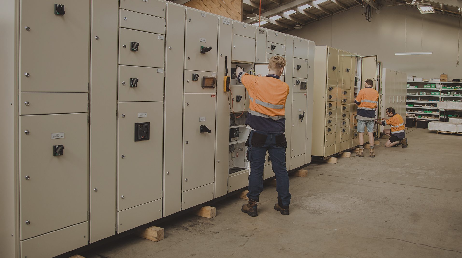
Main switchboards around your supply.
A main switchboard is the point where the site’s supply arrangement becomes a practical distribution system. Its design needs to reflect normal operation, maintenance shutdowns, supply interruptions and future changes, not only today’s total connected load.
We review the incoming supply, outgoing feeders and operating scheme with the consultant, contractor or end user. A clear single-line diagram identifies which loads are essential, which supplies may be connected together and what must remain isolated.
Single incomer, dual incomers or bus coupling
The number of sources and the permitted switching states determine the incomer and bus-section arrangement. Where a coupler is proposed, identify the normal position, the allowed alternative states and the interlocking needed to prevent unintended connections.
Generator and alternative-supply interfaces
Specify manual or automatic changeover, the loads to be supplied and the control interfaces required. Neutral and earthing arrangements, protection settings and operating sequences need project-specific design. Parallel operation is not assumed merely because two incomers are provided.
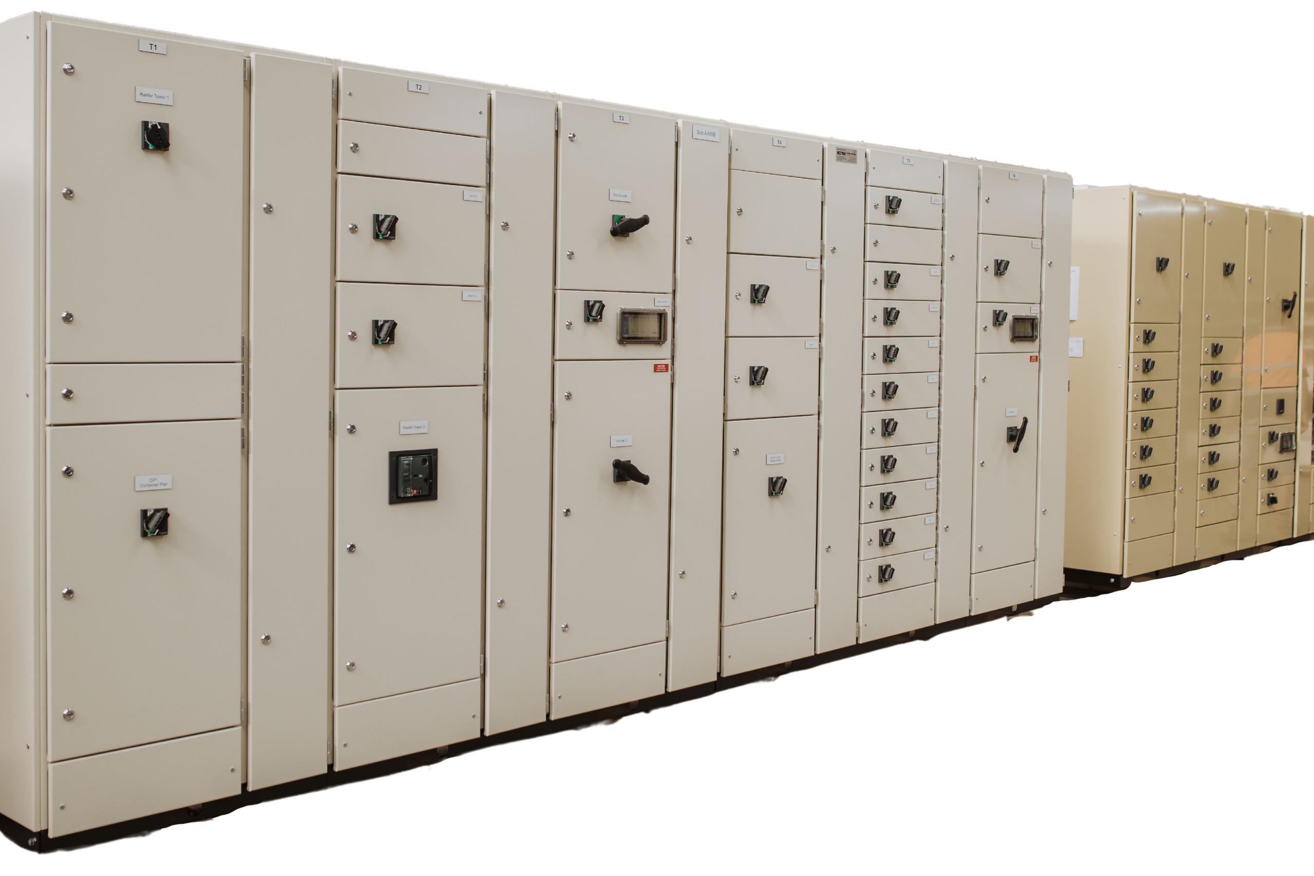
Ratings that fit the assembly.
Current capacity, fault withstand and environmental protection describe different characteristics. They need to be compatible within the actual assembly, including its busbars, supports, connections, devices, enclosure and operating conditions.
| Requirement | What needs to be established |
|---|---|
| Continuous load | The required assembly current, circuit loading, operating duty and allowance for simultaneous demand. |
| Available fault current | The prospective fault level at the board, with the relevant source arrangement and upstream protection information. |
| Short-time withstand | The specified current and duration. A kA figure without a time does not fully describe a short-time withstand requirement. |
| Device breaking capacity | The protection device’s fault-interruption capability at the operating voltage, distinct from assembly withstand. |
| Enclosure and temperature | IP requirements, ambient conditions, ventilation, internal heat and the effect on usable current capacity. |
| Separation and access | The required form of internal separation, cable termination arrangement and maintenance access. |
Simotrol main switchboards: our primary platform for MSB manufacture. The current, fault withstand, separation and enclosure requirements are confirmed for the specified assembly. Explore Simotrol switchboards
Other platform options: Logstrup LV capability extends to 8,000 A where the project calls for it. This is platform capability; the completed assembly’s configuration and ratings still require project-specific verification.
Schneider Electric explains why rated current inside an enclosure must account for the completed arrangement. It also distinguishes short-time withstand current and its duration.
Make room for how the board works.
CWS can incorporate single or multiple incomers, bus section and bus-coupler arrangements, automatic or manual generator changeover, power-quality metering, SCADA or BMS communications, power-factor correction and project-specific arc-fault mitigation options where required.
Cable entry and termination
Provide cable sizes, quantities and entry directions early. Parallel conductors, bending space, gland arrangements and termination access can govern the enclosure dimensions just as much as the circuit breakers do.
Metering and protection interfaces
Agree the measurements, metering locations, CT requirements and communications needed by the site. Protection coordination also needs to consider the upstream source and downstream boards, rather than treating each device as a separate selection.
Neutral and power-quality requirements
Describe significant electronic loads, drives, UPS supplies and any proposed power-factor correction or harmonic filtering. These affect the information required for the design review; adding a filter later is not simply a matter of finding an empty compartment.
Maintenance and component replacement
Confirm front or rear access, door clearances, isolation boundaries and how large components could be removed. Do not assume that a board which fits through the room door will also be maintainable in its final position.
Future expansion
Separate spare circuit positions from spare current capacity and physical space for extension. A future feeder needs a suitable connection point, protection, cable access and a verified arrangement, not just an unused opening.
Delivery sections and site connection
Large lineups may need transport sections. Agree the split locations, handling constraints, reconnection responsibilities and site checks as part of the proposal, especially where access is restricted.
Verify the design. Test the build.
Where AS/NZS 61439 is specified, establish the applicable assembly requirements and the design-verification basis for the selected system. Routine verification of the completed board is a separate activity; a factory test sheet alone does not establish every design characteristic.
Agree the handover documents before manufacture: approved and as-built drawings, declared ratings, device schedules, agreed protection settings, routine verification records and the project-specific factory acceptance test results.
Read the manufacturer’s explanation of design and routine verification.
Relevant project experience
CWS manufactured the Form 4 main switchboard and downstream distribution boards for Southern Charity Hospital in Invercargill. The project provides direct evidence of coordinated MSB and distribution-board manufacture for a healthcare facility.
The project also demonstrates the value of defining segregation, changeover, metering, cable interfaces and downstream distribution as part of the complete assembly brief rather than selecting the main breaker in isolation.
Related electrical assemblies
Connect the MSB specification to the downstream motor control centres and distribution boards. For an integrated room package, review our prefabricated switchrooms.
Bring the supply scheme and site constraints together.
Send the SLD, load schedule, transformer or supply information, available fault level, enclosure requirements, metering specification, cable details and delivery programme. Include room dimensions and access restrictions where available.
Can the transformer size alone determine the MSB rating?
No. Transformer capacity is one input. The load, impedance, available fault current, operating arrangement, environment and protective devices also matter. Send the available source data rather than selecting a board on transformer MVA alone.
Can you replace an existing MSB within the same footprint?
Provide dimensions, photographs, cable entry details and shutdown constraints. We can assess the proposed scope, but the existing footprint is not assumed to provide enough space for the new rating, terminations or access requirements.
Does every project require the same switchboard platform?
Simotrol is our primary platform for main switchboards. Logstrup and Schneider Prisma Plus G or P are further options where the current, fault level, separation, enclosure or project specification calls for them.
Put the requirements
in the brief.
Identify the standard, part and edition, current ratings, fault conditions, environment and verification records required for your project.
Understand the distinction between cited standards and subsequently published editions.
Prepare a switchboard specificationUse the enquiry checklist to prepare a comparable quotation.
Refrigeration and building services.
One main switchboard.
A 630 A Simotrol main switchboard with refrigeration feeders, two integrated distribution boards and coordinated monitoring and protection interfaces. See the completed assembly and workshop construction details.
Explore the cold-storage MSB upgradeStart with the supply.
Build around the site.
Send the single-line diagram, fault information, load schedule and switchroom layout.
Printable quote checklist (PDF)Email your checklist, drawings and schedules to estimating@clivewilson.co.nz. Leave unknown items blank.
Request an MSB quoteOr call +64 3 214 4264Specify the technology your board needs.
Explore arc-flash protection, temperature monitoring, fire-system integration and connected metering options.
Explore switchboard technology