
A main switchboard (MSB) is the principal switching and distribution point for an electrical installation. A distribution board (DB) usually supplies a group of downstream circuits. The difference is their role in the supply system, rather than simply the size of the cabinet. A smaller installation can combine both functions in one assembly.
What do MSB and DB mean in electrical work?
MSB stands for main switchboard. It receives the installation’s incoming supply and distributes power through outgoing feeders. Those feeders may supply distribution boards, motor control centres or large individual loads. Our main switchboard guide explains its components and role in more detail.
DB stands for distribution board. It divides a supply into separate protected circuits, commonly for lighting, socket outlets and other local loads. A DB may serve a floor, tenancy, workshop area or dedicated group of equipment.
“Switchboard” is also a broad term for an assembly used to switch, protect and distribute electricity. That is why drawings and specifications sometimes use overlapping names. Read the board designation alongside the single-line diagram and circuit schedule to understand what it actually supplies.
Follow the supply path
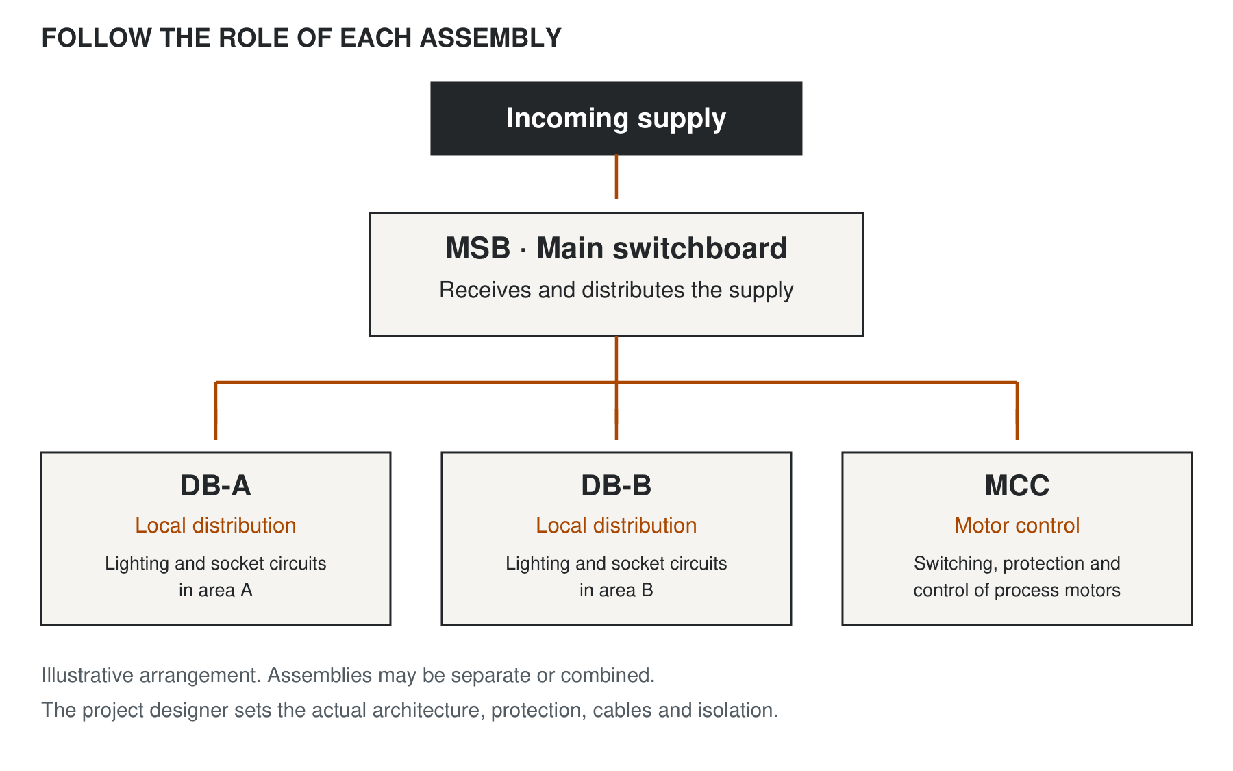
A common arrangement is an incoming supply feeding an MSB, with submains feeding distribution boards around the site. Each DB serves circuits in a particular area or for a particular purpose. This is useful on larger sites because distribution can be located near the loads.
The actual architecture can differ. Multiple supplies, embedded generation and combined boards need their own design. The names describe roles in that system; they are not a substitute for the single-line diagram.
See the supply and distribution roles
Follow the functional boundary rather than the enclosure size. In this illustrative arrangement, the MSB distributes the incoming supply, two DBs serve local final circuits, and the MCC serves process motors.
For later additions, review spare capacity across electrical duty, space and controls. Mechanical-plant control interfaces may also need an MSSB and BMS point schedule.
Main switchboard vs distribution board: key differences
| Feature | Main switchboard | Distribution board |
|---|---|---|
| Position | Principal supply and switching point. | Usually downstream of an MSB or another distribution stage. |
| Circuits | Major feeders, downstream boards and direct loads. | Local distribution and often final circuits. |
| Physical form | Wall or floor mounted, depending on duty. | Wall or floor mounted, depending on duty. |
| Rating | Based on its load and supply conditions. | Based on its own load and fault conditions. |
| Operation | Access and operator requirements defined by the application. | May be intended for ordinary-person operation where the design and applicable standard permit. |
Do not choose the assembly standard solely from the word “DB”. Intended operation and the scope of the relevant standard matter. Likewise, a downstream location does not automatically establish a safe lower fault rating.
A typical commercial building example
Consider a building with offices on several floors and mechanical plant serving the whole site. Its MSB could supply a lighting and power DB on each floor, alongside separate feeders for lifts and a mechanical services switchboard. Each floor DB then distributes power to its local lighting and socket-outlet circuits.
This separates the main supply distribution from local circuit distribution. It also gives the designer a way to organise cable routes, metering and future tenancies. It does not automatically provide fault discrimination or allow every part of the installation to remain energised during maintenance; those outcomes depend on the protection and isolation design.
This is an illustrative arrangement. A hospital, industrial plant or site with a generator, solar or battery supply may need a different configuration. The Southern Charity Hospital project shows a CWS package that included main and distribution switchboards within one building.
Do you need a separate MSB and DB?
A small installation may use one assembly for incoming switching and the final outgoing circuits. A larger building may benefit from separate boards because of cable routes, local isolation, access or future expansion. The electrical designer should establish that architecture.
Think beyond the number of breakers. Consider where the board will be located, who can access it, which loads need continuity and how future changes will be made. Adding several distant circuits to one central board may create a different installation problem from adding a local DB.
Preparing the enquiry
For a coordinated MSB and DB package, identify which assembly each circuit belongs to. A label such as “200 A DB” alone does not tell the manufacturer the outgoing circuit mix, fault duty, enclosure requirements or available cable space. A marked-up drawing and circuit schedule make the intended scope much clearer.
- Show the incoming source and downstream boards on the single-line diagram.
- Provide a circuit schedule for every assembly.
- Confirm current, fault and protection requirements at each location.
- Define mounting, cable entries, available space and environmental conditions.
- Identify RCD, metering and other functional requirements with the designer.
- Allow for the agreed future loads and safe access.
CWS builds main switchboards and lighting and power distribution boards in Invercargill for projects across New Zealand. Where a project includes both, we can discuss consistent components and documentation while selecting each assembly for its particular duty. Use our switchboard quote information guide to prepare the enquiry.
Common MSB and DB questions
What is an SMDB?
SMDB usually means sub-main distribution board. It describes an intermediate distribution stage between the main switchboard and downstream boards or loads. Confirm the intended role from the project drawings because naming conventions vary.
Is an MSB the same as an MCC?
No. An MSB provides the main supply distribution function. A motor control centre groups the switching, protection and control needed for motors. The two functions can form part of a coordinated installation or combined assembly. See our MSB vs MCC comparison.
Is a distribution board always wall mounted?
No. Mounting depends on the design, capacity and site requirements.
Does a DB always have a lower fault rating than the MSB?
Do not assume so. Establish the conditions at each point from the actual system, including other sources.
Further reading: Schneider Electric’s Electrical Installation Guide on distribution switchboards explains main, sub-distribution and final distribution assemblies. Its LV circuit configuration guide covers different supply arrangements.