
An MSB handles the principal supply and distribution role. An MCC groups the switching, protection and control of motor circuits. Many process sites need both, while some projects combine functions in one engineered assembly.
A direct comparison
| Decision | Main switchboard | Motor control centre |
|---|---|---|
| Primary job | Receive and distribute the installation’s supply. | Distribute, switch, protect and control motor circuits. |
| Typical outgoing duties | Submains, downstream boards and large loads. | Pumps, fans, conveyors, agitators and other motors. |
| Key inputs | Supply arrangement, load schedule and distribution philosophy. | Motor schedule, starting methods and control philosophy. |
| Controls | Metering, transfer schemes and other specified functions. | Motor commands, status, interlocks and process interfaces. |
| Ratings | Established from the actual supply, loads and configuration. | Established from its own connection point and motor duties. |
Physical size, cabinet colour or brand does not reliably identify the function. Neither does a fixed current range: an MCC can be a substantial assembly, and a small MSB can serve a modest installation.
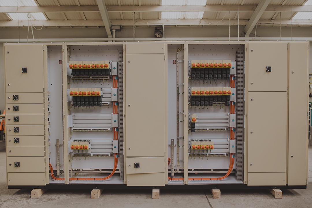
The Frimley and Eastbourne water-treatment package is a CWS example that includes both MSBs and MCCs, alongside distribution and PLC panels. It shows how incoming distribution and individual motor control can be separate assemblies within one coordinated supply package.
Three project situations
A commercial building. The main board may feed lighting and power distribution boards plus packaged building services. If the mechanical contractor supplies complete equipment with its own controls, a separate central MCC may not be needed.
A process plant. The MSB distributes the site supply while an MCC serves a group of pumps, mixers or production motors. The motor circuits need a coordinated control interface with the process system.
A compact pumping installation. Distribution and motor control may be combined where the design, access and verification support it. A combined package still needs the responsibilities and circuit functions clearly defined. These are illustrative arrangements, not prescriptions for a particular project.
Use a function-first decision sequence
- Identify where the installation receives its supply and where it needs principal switching and distribution.
- List the outgoing duties and identify groups of motors needing coordinated switching, protection and controls.
- Locate the loads and consider cable routes, environmental conditions and operating access.
- Compare separate and combined assemblies where both are feasible.
- Confirm the electrical ratings and verification basis for the proposed arrangement.
This sequence keeps the decision tied to the site. It avoids specifying an MCC simply because a project includes one motor, or assuming that a board called an MSB already includes the controls needed for a production line.
Separate assemblies or a combined package?
| Consideration | What to discuss |
|---|---|
| Location | Whether distribution and motor-control functions are best placed together or near different loads. |
| Outages | Which functions need to be isolated for planned work and how the site will operate during it. |
| Environment | Whether one enclosure arrangement suits all installed equipment and its heat. |
| Expansion | How future distribution feeders and motor units will be added. |
| Responsibility | Who coordinates the complete assembly, drawings, interfaces and verification. |
A combined package can simplify some interfaces, but it does not remove the need to define them. Separate packages can suit a distributed site, but their connecting cables and protection still form one coordinated installation. Cost and footprint should be assessed alongside these operating needs.
Where the interfaces are easily missed
- Who provides and sizes the feeder between the MSB and MCC?
- Who establishes the supply fault conditions and protection settings?
- Are VSDs inside the proposed assembly or supplied separately?
- Who supplies PLC hardware, I/O, software and network configuration?
- Who handles field cabling, motor checks and site commissioning?
- What testing demonstrates the interlocks across package boundaries?
Write these interfaces into the enquiry. A motor list alone does not describe the whole distribution system, and a single-line diagram alone may leave the controls undefined.
Give each supplier the same boundary drawing
Mark each assembly and package on the single-line diagram and identify the scope on both sides of the connection. Then add the controls boundary: hardwired signals, networks, auxiliary supplies and the party responsible for the functional description.
For example, if a drive cabinet is supplied separately, establish who provides its upstream protection, incoming terminals, control wiring and ventilation requirements. Do not let both parties assume that the other has allowed for an essential item.
Compare quotations against those marked boundaries. If one proposal includes the drive hardware and another only allows a feeder, their prices are not directly comparable. Use the quotation comparison guide to check scope and departures before choosing the package.
Choose the arrangement from the duty
Compare the cold-storage main switchboard with the industrial process MCC. Both are 630 A assemblies, but their circuit duties and control interfaces differ. These project examples reinforce why current rating alone does not identify a board’s purpose.
Start with the site electrical architecture, then the load and motor schedules. Confirm separation, environmental conditions, access and future additions for each assembly. Avoid assumptions that an MCC always has a lower fault level or that one form suits every industrial site.
CWS can discuss an MSB, an MCC or a coordinated package. Send the available design information and identify the operating functions that need to be included.
Take the decision into a manufacturing brief
Main distribution brief
Use the switchboard cost-driver guide and the capacity-planning ledger to define present and future distribution duties.
Process motor brief
For pumps and controls use the water and wastewater interface guide; for production environments use the dairy and food-processing MCC guide.
Questions we hear
Is an MCC always downstream of an MSB?
That is a common arrangement, but the actual supply architecture may differ. Follow the project single-line diagram rather than assuming a universal hierarchy.
Should the MSB and MCC use the same platform?
They may, but each assembly must suit its own duties and environment. A coordinated project does not require identical construction for every board.