
Form of separation describes the internal arrangement of busbars, functional units and cable terminals. It helps define access and compartment boundaries. It does not, by itself, establish arc-fault containment or make live work safe.
What is being separated?
A functional unit is the equipment serving a particular function, such as an outgoing feeder or motor starter. The form describes how that unit, the main busbars and terminals for external conductors are separated. Barriers, partitions and other permitted construction methods create those boundaries.
Start with the maintenance task you need to support. Where will a technician isolate the circuit? Which cable terminals need access? What other sources could remain present? A form number is useful only when the actual arrangement answers those questions.
Forms at a glance
| Form | Internal separation |
|---|---|
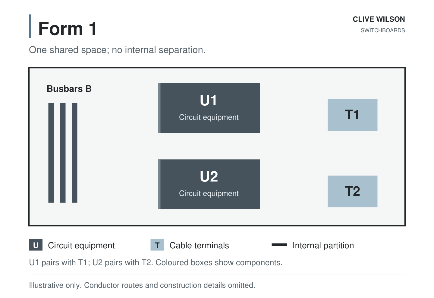
| 1 | No internal separation between busbars, functional units or external cable terminals. |
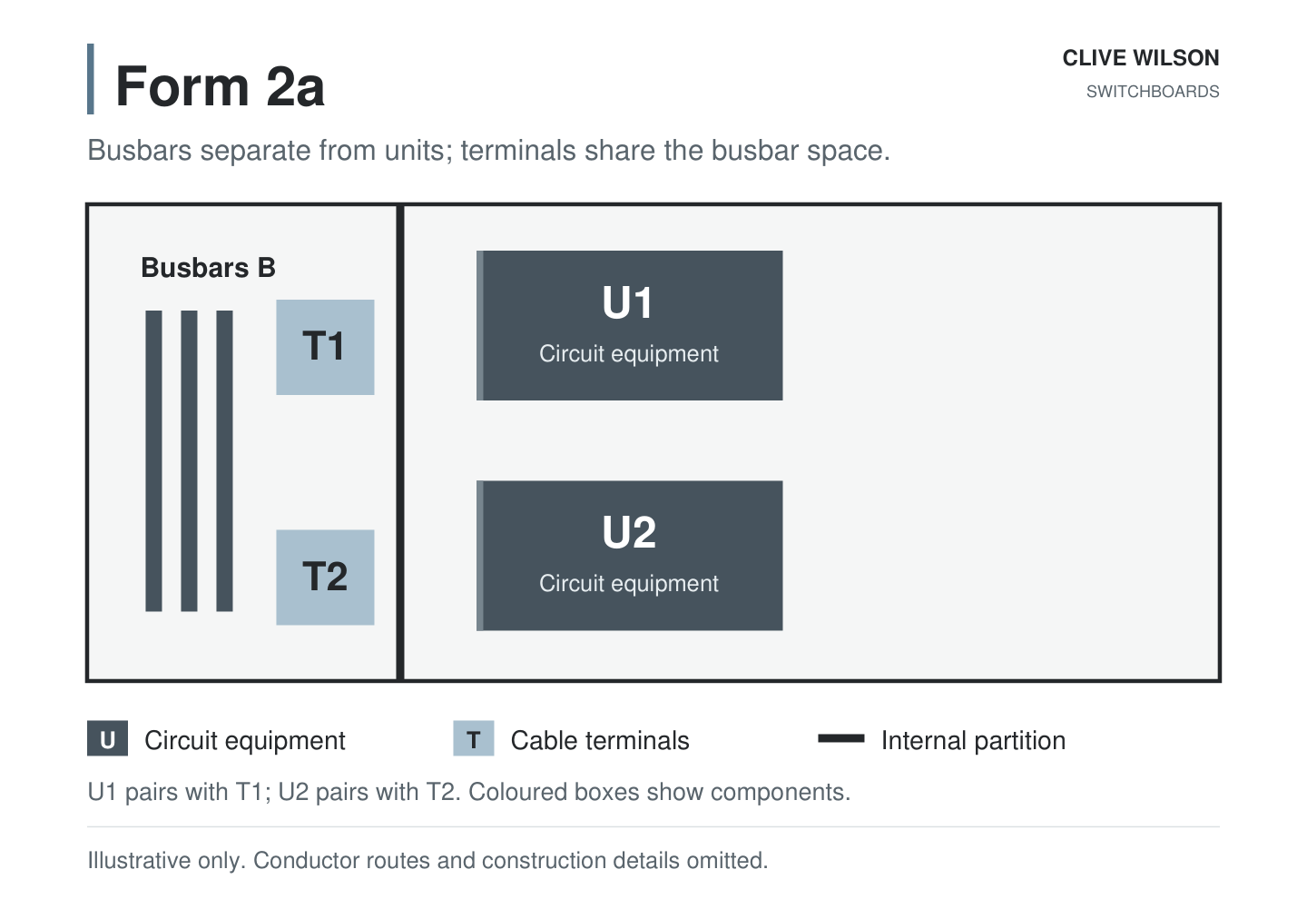
| 2a | Busbars separated from functional units; external terminals not separated from busbars. |
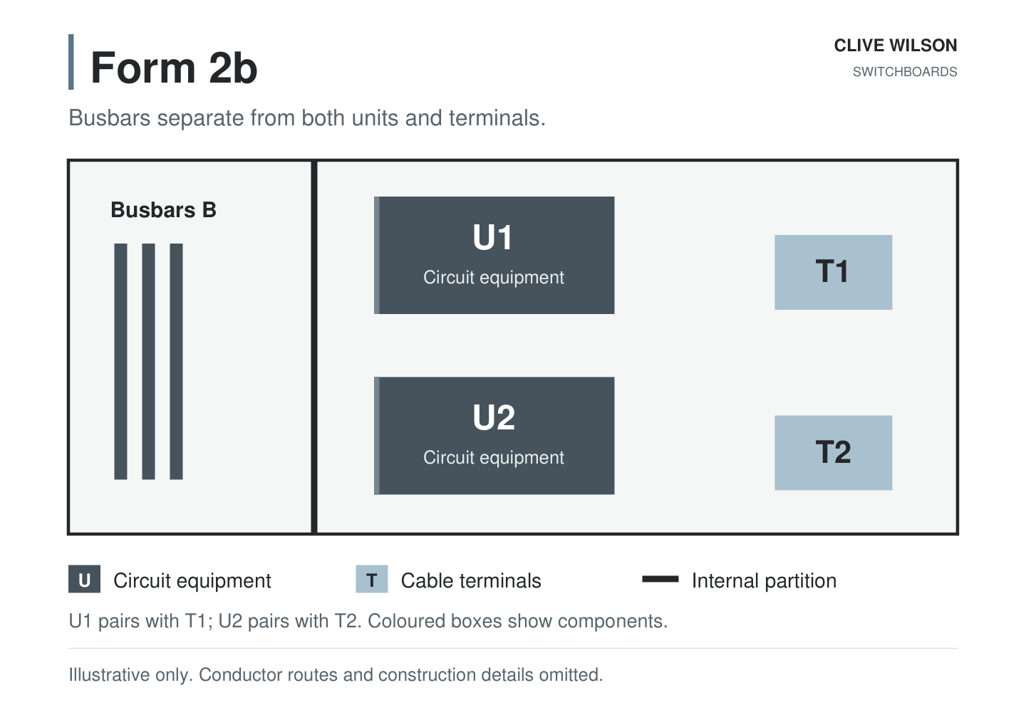
| 2b | As Form 2, with external terminals separated from busbars. |
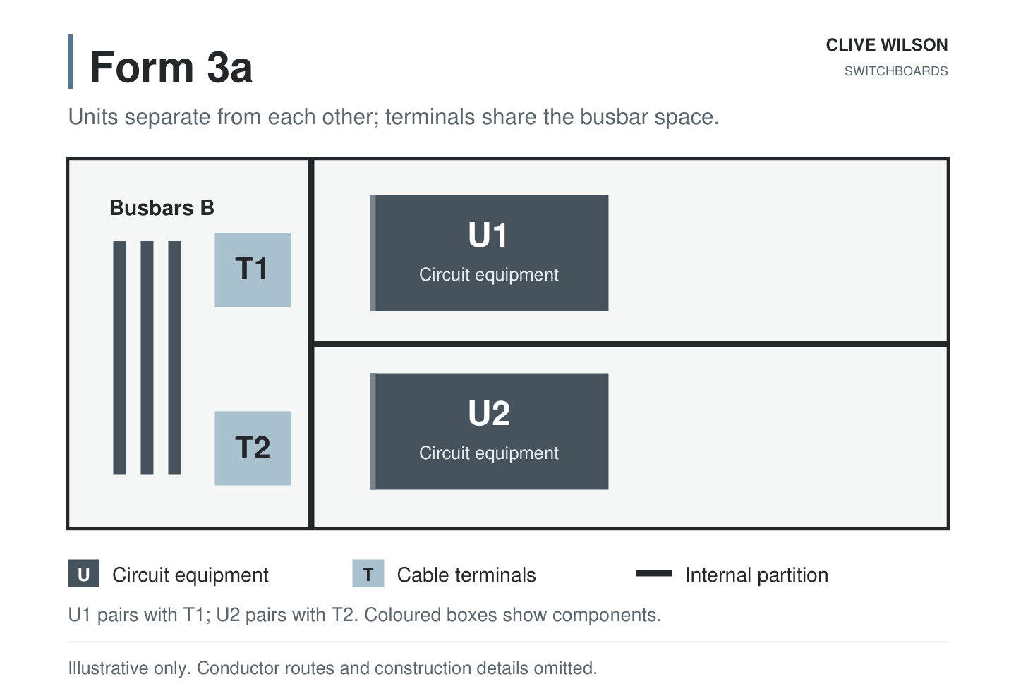
| 3a | Busbars separated from functional units, and units separated from one another. External terminals are separated from the units but not from busbars. |
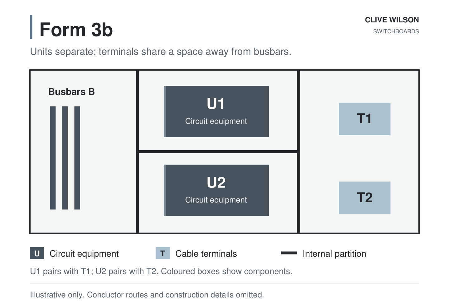
| 3b | As Form 3, with external terminals separated from busbars; terminals for different units may share a space. |
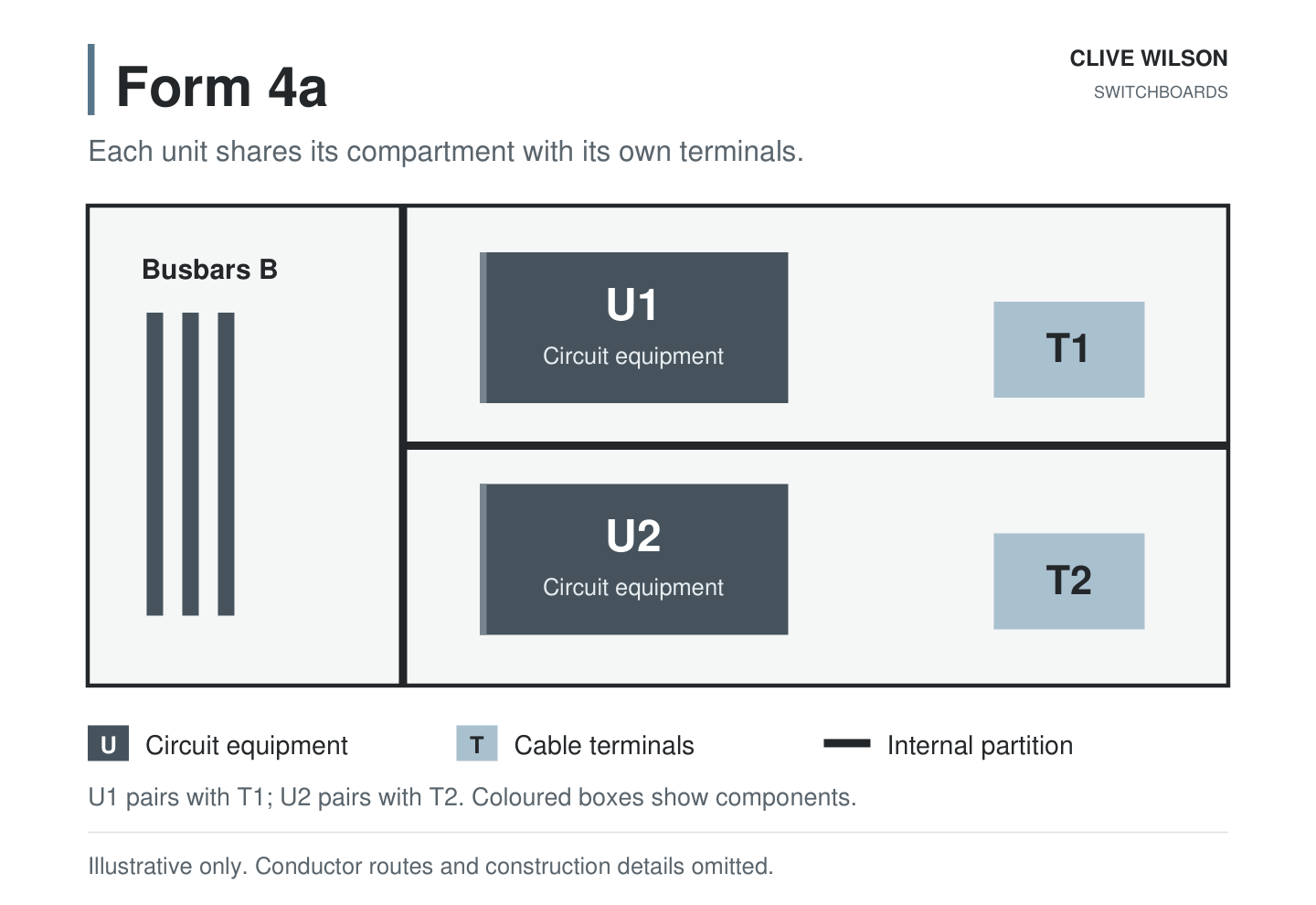
| 4a | Separation extends to terminals for different functional units; each unit’s terminals are in its own unit compartment. |
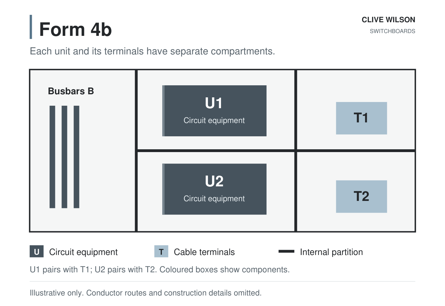
| 4b | Terminals for different units have individual, separate protected spaces outside their associated functional-unit compartments. |
These are short descriptions. Specify the detailed cable and terminal arrangement, including external conductors and neutral conductors where relevant, against the applicable assembly standard. The international guides below help illustrate the layouts; their national annexes are not automatically New Zealand requirements.
Diagram examples for each form
Each diagram uses the same two circuits so the compartment differences are easy to compare. B means busbars; U1 and U2 are circuit equipment, such as feeders or motor starters; T1 and T2 are their external cable terminals.
Thick dark lines show partitions. Grey equipment blocks and orange terminal boxes identify the items; their coloured outlines do not represent extra separation.
Form 1
Form 2a
Form 2b
Form 3a
Form 3b
Form 4a
Form 4b
Use these examples alongside fixed, demountable and withdrawable MCC arrangements. Separation form and how a unit is removed or disconnected are different choices.
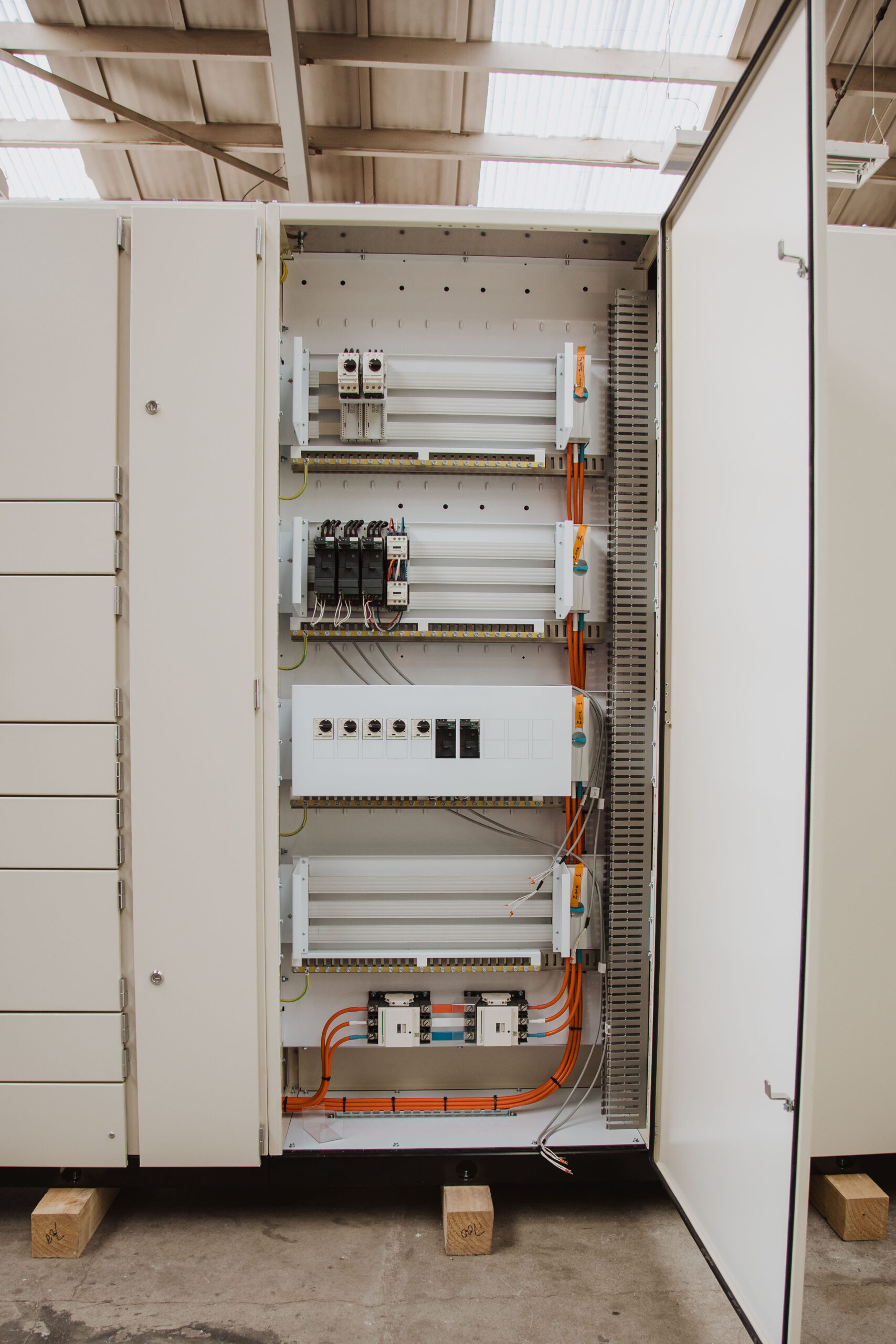
Form 4a or Form 4b?
The practical distinction is the terminal location. For a cable-heavy project, a separate termination space may improve access. On another project, keeping the terminals with the functional unit may give a more suitable arrangement. Ask to see the proposed compartment and cable layout before approving the form.
- Check cable size, bending space and termination access.
- Identify access needed for inspection, replacement and future additions.
- Confirm whether modules are fixed, demountable or withdrawable; form alone does not tell you.
- Check how barriers and covers are restored after cable installation.
Describe the task before selecting the form
Consider the work the owner expects over the board’s life: inspecting a connection, changing a starter, adding a cable or replacing a protective device. These tasks require different access. A form number does not show how a cable reaches its terminal or which auxiliary supplies remain present.
For each task, agree the equipment to be isolated, access required and the boundary to adjacent parts. Include the operations and maintenance team while the layout is still being developed. Their experience of the site can expose a problem that a general arrangement drawing alone does not show.
That discussion may support separate terminal compartments, a different cable zone or a revised module arrangement. It may also show that a planned shutdown is needed regardless of the form. The engineering and safe-work decisions belong together.
Fixed, demountable and withdrawable are separate choices
| Arrangement | What to clarify |
|---|---|
| Fixed | How the device is isolated, disconnected and replaced during planned work. |
| Demountable | The connections and mechanical work needed to remove the unit. |
| Withdrawable | The supported positions, isolation features, interlocks and manufacturer service procedure. |
Two boards with the same form may use different module arrangements. Ask the manufacturer to show the proposed construction and explain its service requirements. A withdrawable unit must be operated and maintained under its approved procedure; the label does not make every task safe while the surrounding board is energised.
The Southern Charity Hospital case study records a Form 4 MSB supplied by CWS. That identifies the documented separation level; it does not establish a withdrawable arrangement or permission for live work. Those are separate matters.
Separation is not an isolation procedure
A higher form does not automatically increase the assembly’s short-circuit rating. Fault withstand and any specified internal arc performance need their own evidence. Nor does a form number guarantee that an adjoining section can remain in service during a particular task.
Review the cable arrangement on the drawing
Terminal size and compartment boundaries are only part of the review. Check that incoming and outgoing conductors can be installed with the required bending space, supports and access. Include the neutral and protective conductors and any separate control supplies.
Clarify which parts of the arrangement the assembly manufacturer supplies and which are completed on site. Ask how the intended separation is retained when the installer fits cables and reinstates barriers. Record approved details so future alterations can use the same basis.
For a motor-heavy project, the MCC specification checklist links this layout review to the motor and control schedules. For a distribution assembly, include it in the overall switchboard specification.
What to put in the enquiry
State the required form, outgoing schedule, cable entry arrangement, operating access and maintenance expectations.
CWS standard approach
For industrial motor control centres (MCCs) and main switchboards (MSBs), CWS’s standard approach is Form 4a. For group starter systems, CWS’s standard approach is Form 3bih.
The final arrangement is confirmed against the project specification and the selected assembly configuration. Explore CWS Simotrol MCC configurations when planning the build. Short-circuit ratings and other assembly characteristics are confirmed separately.
Changes to an existing board need an engineering assessment of the affected construction and verification. Adding barriers does not automatically upgrade the declared form, but neither is every alteration automatically a full replacement.
Questions we hear
Does Form 4 mean arc resistant?
No. Internal separation and internal arc performance are different characteristics. Specify and substantiate any arc-performance requirement separately.
Is Form 4b always the best choice?
The right arrangement depends on cable access, maintenance tasks, space and the verified system. Resolve those requirements before choosing the form.
Does Form 4b mean the units are withdrawable?
No. Form describes internal separation. Fixed, demountable and withdrawable construction must be specified and confirmed separately.
References and further reading
Diagram relationships checked 1 October 2026 against the international guides below. Confirm the applicable project standard and declared assembly arrangement.