
The switchboard’s short-circuit capability must suit the prospective fault conditions at its installation point and the protection arrangement. A breaker’s kA rating alone does not establish the rating of the completed assembly.
The ratings describe different things
| Term | Meaning | What to confirm |
|---|---|---|
| PSCC | Prospective short-circuit current at a point in the system. | Source data, fault type, operating configuration and calculation assumptions. |
| Icw | Rated short-time withstand current, stated with a duration. | Both the kA value and time, such as a declared one-second rating. |
| Ipk | Rated peak withstand current. | The required peak duty and verified mechanical withstand. |
| Icc | Rated conditional short-circuit current of an assembly. | The specified protective device and all conditions supporting that rating. |
| Icu / Ics | Circuit-breaker ultimate / service short-circuit breaking capacities. | Device rating at the operating voltage, distinct from assembly withstand. |
A statement such as “50 kA board” is incomplete unless the relevant rating, time or protective-device conditions are clear. Do not assume that all boards must use the same rating route.
Establish the fault conditions
Obtain the available supply information from the network and the project electrical designer. The calculation needs to reflect the point where the board will be installed, not simply the transformer nameplate.
- Transformer rating, voltage, percentage impedance and source fault contribution.
- Cable or busduct length, size and impedance between source and board.
- Parallel supplies, couplers and possible generator operating modes.
- Motor contributions and other sources relevant to the study.
- Maximum and minimum fault scenarios needed for equipment duty and protection operation.
Protection settings affect clearing time. A current-limiting protective device can also affect the let-through duty. Those effects must be assessed using appropriate device data; they do not replace the prospective fault calculation.
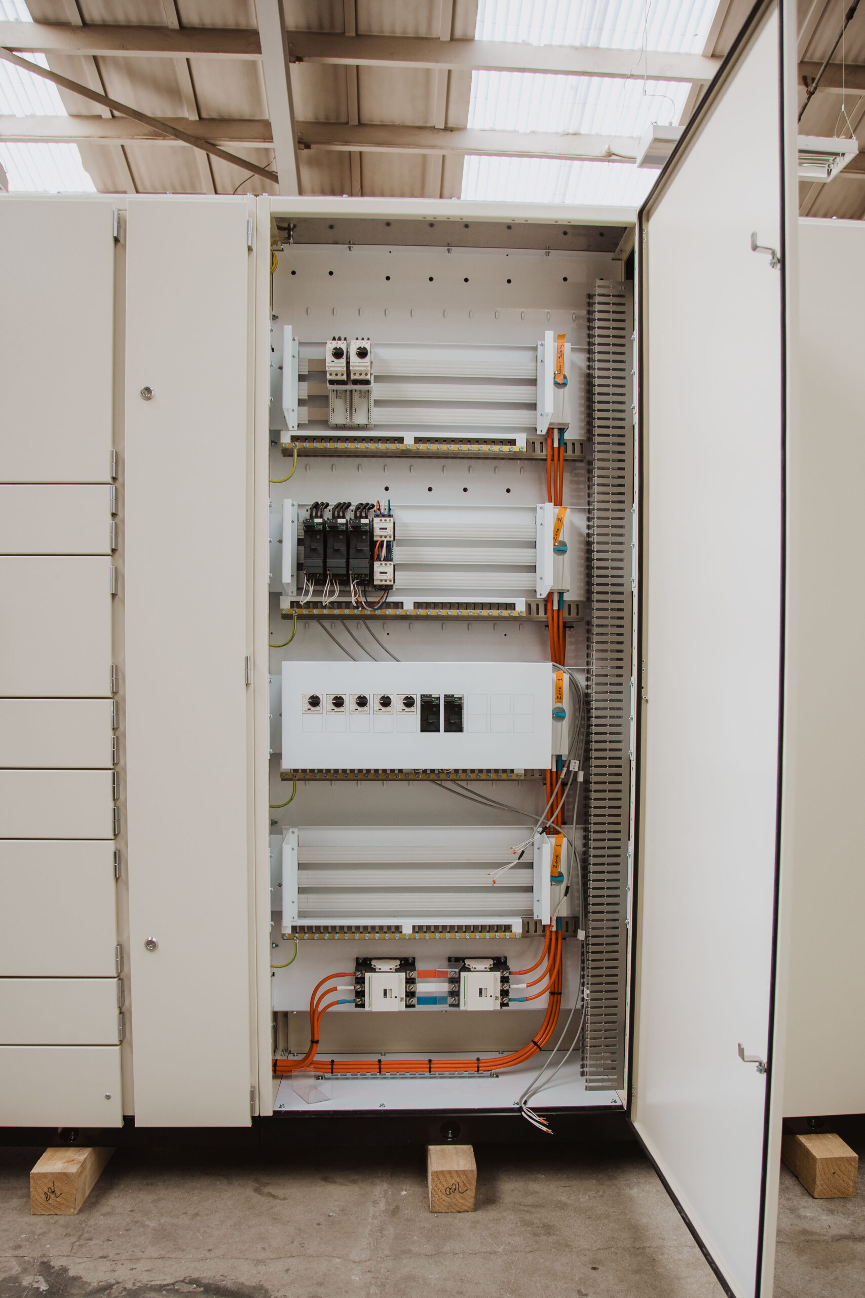
A simple example of why a bare kA number is not enough
Imagine a specification stating only “36 kA”. The tenderer still needs to know whether that means a short-time withstand rating with a specified duration or a conditional rating relying on stated protection. The study also needs to establish the relevant peak duty and operating modes.
Now consider a proposed generator connection or a normally open bus coupler. If the project permits additional sources to operate in parallel, the original duty may change. The assembly and protection must be assessed for the permitted arrangement, not just the single-source drawing used at an earlier tender stage.
This is why a useful requirement refers to the study revision and describes the rating basis. The example is about specifying information; it does not nominate a suitable rating for a real installation.
Current rating and fault rating are not interchangeable
A board’s current rating describes its normal operating duty under the stated conditions. Its fault characteristics address a different, short-duration event. A larger ampere rating does not automatically mean a higher short-circuit rating.
Likewise, the frame size of a breaker does not establish all its protection characteristics. Confirm the actual device version, voltage rating, trip unit and settings. Where cascading or backup protection is used, the documented combination is part of the design basis.
Use estimates for the right purpose
The CWS transformer fault current calculator can help with an early transformer-based estimate. It cannot represent every source, cable, motor or switching arrangement on a real site.
Coordinate the assembly and protection
For a short-time withstand arrangement, check the fault duty and clearing time against the declared characteristics. For a conditional arrangement, check the exact upstream protection and conditions supporting the assembly rating. Backup protection between devices is a further coordination issue and needs documented combinations.
Verification of the assembly covers more than the incoming breaker: busbars, supports, connections, circuit arrangements and protective devices all matter. A satisfactory short-circuit rating is not a claim that an internal arc will be contained or that equipment can remain in service after a fault without inspection.
Reading the records for an existing board
Start with the assembly identity and available manufacturer documentation. Record the declared characteristics, relevant protective devices and any subsequent modifications. If records are incomplete, state the limitation instead of inferring the rating from the appearance of the busbars.
Compare the documented duty with the current supply study. A transformer replacement, additional source or change to protection can affect suitability even when the connected load has not increased. Conversely, a visually old board is not automatically under-rated.
- Confirm the study applies to the actual installation point.
- Identify every permitted source configuration.
- Check the stated time or protective-device conditions.
- Record any differences between the installed and documented equipment.
- Assign the engineering assessment before procurement or modification.
For wider replacement planning, use the upgrade and replacement guide.
A useful fault-rating brief
Send the fault-study reference and revision, operating voltage, required assembly rating, protective-device details, clearing-time basis and any future supply changes. State who is responsible for the system study and who will approve protection settings.
CWS uses this information to select and document an appropriate switchboard configuration. The published 50 or 63 kA for one second options for particular Simotrol MCC arrangements are configuration-specific, not default ratings for every CWS assembly. See main switchboards or motor control centres for the manufacturing scope.
Questions we hear
Can I use the incomer’s breaking capacity as the board rating?
No. Device breaking capacity and assembly short-circuit capability must each be established for the installation.
Does a higher kA rating always improve the design?
It may be required for future supply conditions or a project standard, but the decision needs an engineering basis. Assess present and planned duty, verification and protection coordination together.
Does normal load current tell me the available fault current?
No. Load current and prospective fault current describe different conditions. The source and network impedances and relevant contributions establish the fault conditions.