What Is a Motor Control Centre? How MCCs Power Process Plants
The motor control centre is the assembly that powers, protects and switches the main motor loads on a process plant. Get it wrong and you stop production. Get it right and operators barely notice it is there.
CW
Chris Wilson, Co-Director, Clive Wilson Switchboards Registered electrician, EEHA-qualified, 15+ years LV switchboard experience
Quick answer
A motor control centre (MCC) is a low-voltage switchgear and controlgear assembly that distributes power, provides motor protection, and houses the local control for the main motor loads on a process plant. It sits downstream of the main switchboard, uses DOL and soft-start modules for in-cabinet starting, and supplies external VSDs where speed control is needed. Designed and verified to AS/NZS 61439, sized from the motor list, and commonly specified as Form 4a for dairy, freezing works and water treatment sites.
This guide covers what a motor control centre is, what goes inside one, how to size one for a New Zealand site, and what to plan for when replacing or upgrading an existing MCC. Clive Wilson Switchboards, based in Invercargill, has been building MCCs for industrial sites across New Zealand for over 55 years. Here is what you need to know.
What does a motor control centre actually do?
An MCC performs four core functions on a process plant. Each one matters, and the design choices for each one drive the rest of the design decisions.
1.Bulk power distribution: takes a single feeder from the main switchboard and distributes it across a busbar system that runs the length of the lineup.
2.Motor starting: provides direct online (DOL) and soft-start modules for each in-cabinet motor on the plant.
3.VSD supply feeders: provides feeders out of the MCC to variable speed drives that sit external to the assembly in their own drive cabinets or wall-mounted enclosures.
4.Local control and PLC interface: houses local-off-remote selection, manual start and stop pushbuttons, thermistor reset and run/trip indication on each module door, plus the wiring back to the plant PLC.
The MCC is built to AS/NZS 61439 parts 1 and 2 (assemblies and power assemblies), installed under AS/NZS 3000, with cables sized to AS/NZS 3008.
MCC vs main switchboard, what is the difference?
The main switchboard (MSB) and the motor control centre sit at different points in the distribution chain and do different jobs.
Main switchboard (MSB)
Receives the incoming utility supply
Provides the main isolator and metering point
Distributes feeders to sub-boards, MCCs, distribution boards and large single loads
Carries the highest current and fault rating in the installation
Motor control centre (MCC)
Sits downstream of the MSB, fed by a single dedicated feeder
Distributes primarily to motor loads
Contains starter modules, motor protection and the control logic interface to the PLC
Sized to the motor list, not the whole-of-site load
For a longer explainer on what an MSB is and what it must contain, see our guide What Is a Main Switchboard?
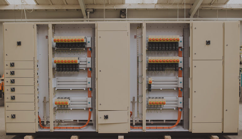
What goes inside a motor control centre?
An MCC is built up from a busbar system, a set of motor starter modules, the protection devices for each module, the local control on each module door and the marshalling cabling back to the plant PLC.
Starter modules
Direct online (DOL) for smaller motors where full-voltage start is acceptable.
Soft-start modules for larger motors and applications that need controlled acceleration to limit inrush and mechanical shock.
VSD supply feeders out of the MCC where the load needs speed control. The drive itself is mounted in a separate drive cabinet, or wall-mounted in its own enclosure, sized for cooling and any harmonic mitigation.
Protection
Motor protection circuit breakers (MPCBs) or moulded case circuit breakers (MCCBs) on each module.
Contactors rated to AC-3 utilisation category, sized to the motor.
Thermistor input where the motor has PTC sensors fitted, with a reset button on the module door.
Overload protection coordinated with the motor data sheet.
Door-mounted controls
Local-off-remote selector switch
Manual start and stop pushbuttons
Thermistor reset
Run and trip indication lamps
Ammeter where the motor calls for it
Emergency stop where the process or safety case requires it
Communications and PLC interface
PROFIBUS, Modbus TCP, EtherNet/IP and Modbus RTU back to the plant control system.
Schneider PLC integration with Modicon M340 and M580 process controllers, paired with X80 I/O modules and Advantys distributed I/O blocks where the application calls for them.
Marshalling cubicle, I/O terminals and intrinsically safe barriers where the application is in a hazardous area.
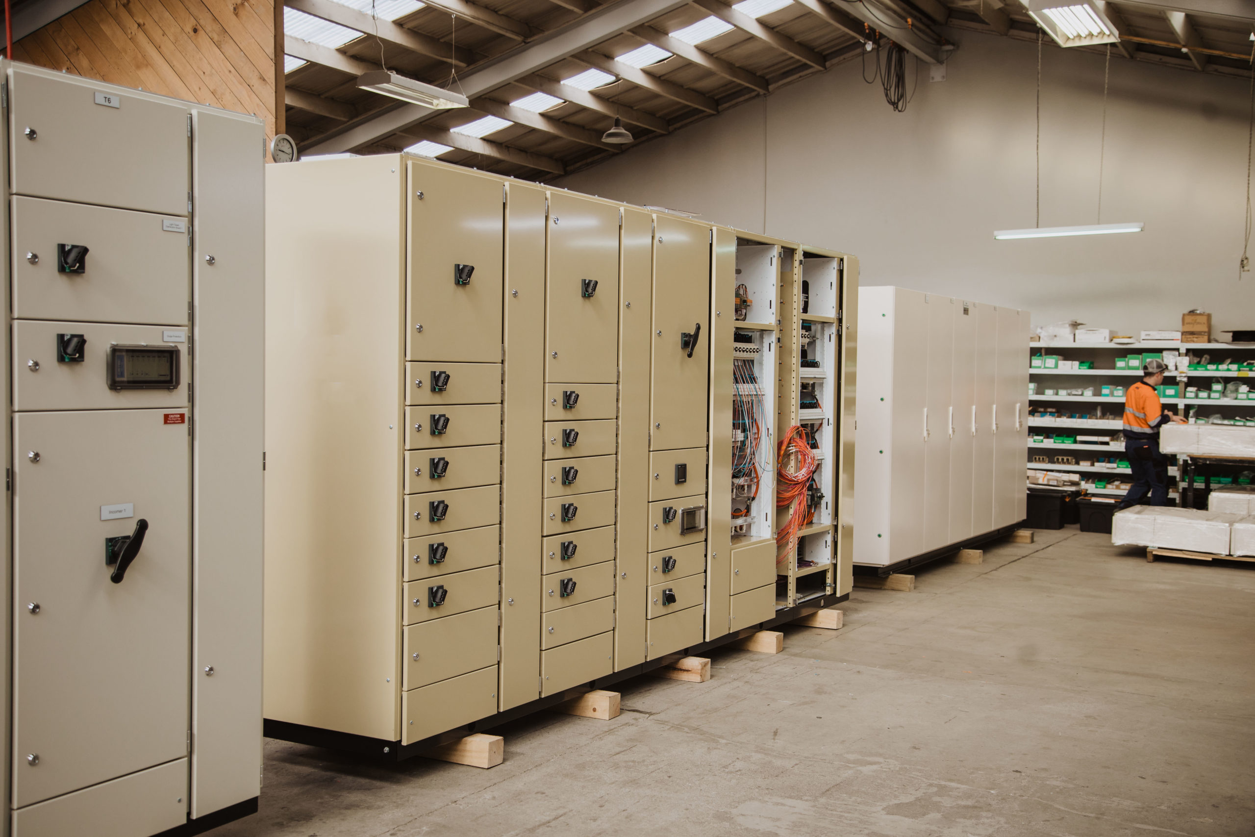
Module construction
Demountable modules are our standard MCC construction. Each module bolts in place and unbolts for replacement or maintenance once the section is isolated.
Withdrawable modules on the Logstrup platform are available on request where the project specification calls for them.
Engraved Traffolyte or laser-engraved labels through our in-house engraving line.
Builder’s note: On CWS MCC projects, VSDs are normally kept out of the MCC. The MCC supplies the feeder, but the drive itself lives in a dedicated cabinet alongside or wall-mounted, sized for cooling and any harmonic mitigation. This helps keep the MCC compact, avoids heat soak from the drives, and means a drive replacement does not require opening the MCC.
How do you size a motor control centre?
Sizing an MCC starts with the motor list and works back through busbar current, fault withstand, form of internal separation, enclosure rating and platform choice.
Motor list
Every MCC project begins with a clean motor list. For each motor we need to know:
Rated power (kW) and rated voltage
Full load current, starting method and expected starting current
Start type (DOL, soft-start, or VSD-fed)
Duty cycle and ambient temperature at the motor location
Whether the motor has PTC thermistors and whether the duty calls for them
Whether the motor sits in a hazardous-area application
From the motor list we work out total connected load, diversity factor, expected operating load and busbar current required. The fault level at the MCC busbar comes from the upstream transformer impedance, upstream protection settings and the cable run from the main switchboard. Our NZ Transformer Fault Current Calculator gives a first-pass estimate of prospective short-circuit current you can use as a starting point.
Form of internal separation
The form of internal separation defines how separated the live parts of each module are from the busbars and from the other modules. Forms 1 through 4b describe increasing levels of internal separation used when specifying AS/NZS 61439 assemblies.
Form 2 separates the busbars from the functional units but does not separate units from each other
Form 3 also separates the functional units from each other, but terminals stay with their unit
Form 4 separates busbars, functional units and terminals from each other
Form 4a places each functional unit’s terminals in the same compartment as the unit itself, and is the standard segregation on CWS Simotrol MCCs for dairy, freezing works and water treatment sites
Form 4b places each functional unit’s terminals in a separate compartment from the unit, specified where the highest level of segregation is required
For a longer treatment of Form classifications, see our guide on forms of segregation.
Enclosure and IP rating
Most MCCs are designed as indoor assemblies. We build to IP41 through IP55 indoor enclosures with gland plates as required. If the MCC needs to sit somewhere the environment is harsher than a normal switchroom, the room itself or a kiosk needs to bring the environment back to indoor conditions before the MCC is installed.
Platform: Simotrol or Logstrup
We build on two type-tested platforms:
Simotrol, CWS’ in-house platform for MSBs and MCCs, AS/NZS 61439 type-test backed, suits the majority of NZ dairy, freezing works, water and pump-station MCC projects.
Logstrup, available where the project specifies withdrawable modules or a specific busbar architecture.
For sites that want platform consistency between the upstream MSB and the MCC, we can build the MCC on the same platform as the upstream MSB.
The motor list is the single most important document on any MCC project. Get the kW ratings, start types and thermistor flags right at enquiry, and engineering can begin the same day. Get them wrong and the whole programme slips.
How do you replace an existing MCC on a live plant?
Replacing an MCC on a live process plant is a different problem to a greenfield build. The plant often cannot stop running while you swap it out, the existing cabling and motor terminations need to land back in the new assembly, and the new MCC has to fit the same footprint and cable entry points.
Before you start
Capture the existing motor list, including any motors added since the original install. The original schedule is often no longer current.
Confirm the existing busbar rating, fault withstand and form of internal separation. If those are not documented, verify during a planned shutdown.
Map the existing cable routes, gland plate positions and terminal numbering. The new MCC needs to land cables in the same physical positions.
Identify any equipment that is past end of life and needs replacement at the same time, such as obsolete contactors or soft-starters.
Plan the shutdown window with the operations team. Most dairy and freezing works MCC replacements happen during seasonal shutdowns.
Pre-fit and factory acceptance test the new MCC before site arrival.
Stage the cable termination work so the longest cable pulls happen first.
Have a contingency plan for any motor circuit that does not start cleanly on energisation.
Builder’s note: The biggest single mistake on MCC replacements is assuming the existing schedule reflects what is actually wired up. Confirm motor-by-motor with the operations team before tendering. The cost of finding an undocumented 75 kW motor halfway through cable termination is far greater than the cost of an extra walk-through.
Lead times on a custom MCC are typically 8 to 14 weeks from sign-off to factory acceptance test, depending on size and component availability. See our switchboard lead time guide for what shifts the timeline.
Frequently asked questions
What is the difference between an MCC and a main switchboard?+
A main switchboard receives the incoming utility supply and distributes feeders to sub-boards, MCCs, distribution boards and large single loads. A motor control centre sits downstream of the MSB, takes a single feeder from it, and distributes power only to motor loads. The MSB carries the highest current and fault rating; the MCC is sized from the motor list, not to the whole-of-site load.
Are VSDs mounted inside the MCC?+
No. The MCC provides a VSD supply feeder, but the drive itself is mounted in a dedicated drive cabinet alongside the MCC or wall-mounted in its own enclosure. This keeps the MCC compact, avoids heat soak from the drives, and means a drive replacement does not require opening the MCC.
Are starter modules demountable or withdrawable?+
Demountable as standard. Each module bolts in place and unbolts for replacement or maintenance once the section is isolated. The Logstrup platform offers fully withdrawable modules on request where the project specification calls for them.
What form of internal separation do most MCCs use?+
Form 4a is the most common in NZ dairy, freezing works and water treatment MCCs on the CWS Simotrol platform. It separates busbars, functional units and terminals from each other, with each functional unit’s terminals housed in the same compartment as the unit itself. Form 4b (terminals in a separate compartment) is specified where the highest level of segregation is required. Lower forms (Form 2 or 3) are still used where the duty does not justify a Form 4 build.
Can an MCC be installed outdoors?+
Most MCCs are designed as indoor assemblies. If the location is harsher than a normal switchroom, the room itself or a kiosk needs to bring the environment back to indoor conditions before the MCC is installed. We build to IP41 through IP55 indoor enclosures with gland plates as required.
How long does a custom MCC take to build?+
Typically 8 to 14 weeks from sign-off to factory acceptance test, depending on size, platform and component availability. Specialist soft-starters and protection relays are the categories most likely to carry extended supplier lead times.
Do you integrate Schneider PLCs?+
Yes. We wire and commission PROFIBUS, Modbus TCP, EtherNet/IP and Modbus RTU back to the plant control system. For Schneider PLC integration we routinely build with Modicon M340 and M580 process controllers, paired with X80 I/O modules and Advantys distributed I/O blocks. The PLC hardware itself is usually housed in a separate control cubicle attached to the MCC or remote-mounted.
Send us your motor list, single-line diagram and a confirmed fault level, and we will scope your MCC on the Simotrol or Logstrup platform. Based in Invercargill, building MCCs and main switchboards for NZ industrial sites since 1971.