
Agree the acceptance basis before booking the visit
A factory visit is too late to discover that the customer expected an integrated control demonstration while the supply order covered panel wiring only. Agree the factory acceptance test plan during design: the equipment included, documents to review, functions to demonstrate, people attending and the evidence required for release.
Identify dependencies such as free-issued PLC hardware, software, relay settings, network access and simulation equipment. If something will not be available, agree what can be checked at the factory and what remains for later. State whether a witness point requires customer attendance or allows the work to proceed after an agreed notice period.
Separate three different kinds of evidence
| Evidence | Purpose | What to ask for |
|---|---|---|
| Design verification | Supports the assembly design and its declared characteristics. | The basis covering the actual configuration, including relevant departures. |
| Routine verification | Checks the completed assembly for manufacturing and functional issues within the required scope. | Identified records for the manufactured board and the applicable requirements. |
| Project FAT | Records the agreed customer acceptance checks and demonstrations. | An approved procedure, results, witness record and action list. |
A project FAT is not a substitute for design verification or routine verification. Equally, a routine-verification record does not automatically demonstrate every customer operating sequence. Schneider Electric’s panel-building guidance makes the distinction between design evidence and completed-assembly verification.
Destructive short-circuit testing is not something a customer should assume will be performed on each completed project board during a witness visit. Ask how the required characteristic is supported and how that evidence relates to the board being accepted.
Walk through the assembly systematically
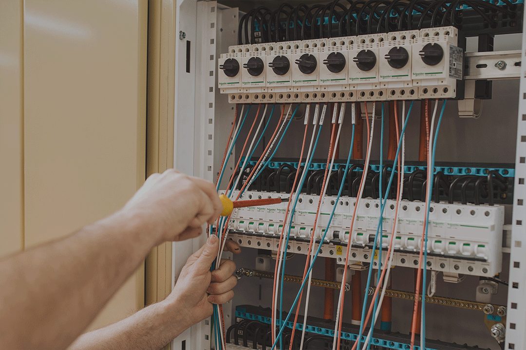
Begin with identity and configuration. Check the board designation, drawings, nameplate information, equipment references and circuit labels against the accepted documents. Confirm that cable access, external terminals and installation interfaces match the agreed arrangement.
Then review the completed verification records with the responsible test person. The applicable test methods and acceptance criteria come from the agreed standard, manufacturer instructions and project procedure. A visitor’s checklist should not prescribe a universal dielectric-test voltage or encourage testing connected electronics contrary to their instructions.
Physical inspection also helps identify handover problems: an unreadable label, missing access cover, undocumented terminal change or unclear transport joint can become costly when discovered on site. Record these precisely with the location and the required resolution.
- Use competent test personnel and the factory’s controlled test arrangements.
- Confirm any temporary links, simulation connections or test settings are identified.
- Record results and evidence rather than marking broad headings “all OK”.
- Keep the witness activity within the agreed safe access and test procedure.
Demonstrate functions with an expected result
For a motor feeder, a useful test describes the initial state, action and expected response. “Check motor control” is too vague. A better test might simulate a run command in the agreed mode and record the resulting contactor or drive indication, returned status and response to an introduced fault.
Control demonstrations should cover the approved sequence, including relevant permissives, local/remote authority, loss of a signal and restoration. The project designer decides the required behaviour. Do not assume that restarting automatically after power or communications return is appropriate.
| Test | Expected result to agree | Evidence |
|---|---|---|
| Local/automatic selection | Only the intended command source has authority; agreed interlocks remain effective. | Mode indications and observed outputs recorded. |
| Feeder trip simulation | The specified trip indication and reset behaviour occur. | Signal source, indication and reset result recorded. |
| Loss of communication | The approved fallback behaviour occurs and the fault is visible. | Simulated condition and actual response recorded. |
| Restoration | The agreed recovery sequence occurs without an unintended command. | Recovery state and outstanding dependencies recorded. |
These examples are a starting structure, not a complete safety-validation procedure. Where the FAT uses simulated signals, identify that fact. It does not prove the performance of field sensors, actual motors, plant hydraulics or networks that were not present.
Turn findings into a release decision
Each finding needs a unique reference, location, description, responsible party and required completion date. Agree which items prevent dispatch, which require a repeated test and which can be completed through an expressly accepted handover action.
A signature should identify what was witnessed and accepted. It should not quietly transfer responsibility for untested work or imply that every installation requirement has been completed. Record absences, simulations and exclusions alongside the results.
Before release, close the agreed actions, confirm the final document revisions, restore the intended configuration and arrange the specified packing and transport information. Any later alteration should be reviewed for the tests and records it affects.
Carry the right information to site
The handover package should connect the manufactured equipment to its drawings, settings, verification records, manuals and outstanding site tests. Identify who completes external terminations, protection commissioning, PLC integration, field-loop checks and installation certification.
For NZ work, WorkSafe treats installation testing and certification as distinct requirements. A successful factory acceptance visit does not replace those obligations.
The published 2026 assembly editions are AS/NZS 61439.1:2026 and AS/NZS 61439.2:2026. Identify the project’s actual part and edition on the test plan. WorkSafe’s installation guidance specifies AS/NZS 3000:2018 with Amendments 1, 2 and 3 from 13 November 2026, subject to the applicable transition provisions; that change should not be described as automatically mandating the 2026 assembly editions.
Bring FAT requirements into the switchboard specification before manufacture. That allows CWS to define the people, equipment, time and evidence needed for acceptance.
References and further reading
- AS/NZS 61439.1:2026, Standards Australia catalogue
- AS/NZS 61439.2:2026, Standards Australia catalogue
- Schneider Electric: assembly design and routine verification
- Schneider Electric: quality inspection, packing and installation
- WorkSafe: low and extra low voltage electrical installations
- WorkSafe: electrical installations and the 2025 amendment transition