
A useful MCC brief connects every motor to its starting method, protection, control interface and operating duty. Resolve those details alongside the supply, enclosure and installation requirements before ordering equipment.
1. Build a motor schedule that can be used
| Field | Why it matters |
|---|---|
| Tag and description | Connects the motor to drawings, labels and process equipment. |
| Rated voltage, kW and current | Establishes equipment selection inputs. |
| Duty and starting frequency | Affects starter selection and thermal duty. |
| Starting method | Identifies DOL, soft starter, drive or another arrangement. |
| Motor and process protection | Defines sensors, trips and reset requirements. |
| Local and remote controls | Defines selectors, I/O, status and communications. |
| Supply and installation notes | Records cable information, location and special constraints. |
Use one row per motor and identify spare or future circuits separately. Mark uncertain data rather than assigning a generic value. Name the person responsible for confirming the schedule.
A worked motor-schedule extract
The following extract is illustrative, not a CWS client schedule. It shows a useful way to distinguish a selected process requirement from technical information still awaiting confirmation.
| Field | P-101: inlet transfer pump | P-102: standby transfer pump |
|---|---|---|
| Process duty | Lead pump; flow controlled to the approved process brief. | Standby duty; changeover behaviour to be confirmed by the process designer. |
| Starting method | VSD requested; exact drive model not yet approved. | Starting method awaiting the designer’s selection. |
| Nameplate and supply data | Motor datasheet required: voltage, rated current and duty. | Motor datasheet required: voltage, rated current and duty. |
| Commands and status | Local/off/remote requirements; run, available and fault signals to be scheduled. | Standby availability, run and fault signals to be scheduled. |
| Protection and safe functions | Protection inputs and safety-function responsibility remain open design items. | Confirm required protection and the same responsibility boundaries. |
| Ownership | Designer confirms motor duty; integrator confirms logic and I/O; supply scope agreed with CWS. | Record an owner and due date for every open item. |
On a small screen, scroll the table sideways to read every column.
A blank marked “awaiting data” is more useful than a guessed motor current or an unspecified network interface. Coordinate the motor schedule, drawings and control philosophy to the same revision.
Resolve the equipment duty
Compare DOL, soft starter and VSD starting; then use the VSD heat-loss worksheet when drives will be integrated.
Resolve the handover
Agree the FAT witness and record requirements and future-capacity allowances before those choices affect the layout.
2. Resolve drive location and thermal duty
Identify which drives are supplied by CWS, by another contractor or as part of packaged equipment. Confirm exact models when selected, and provide manufacturer data needed for heat, clearance, ventilation and protection design.
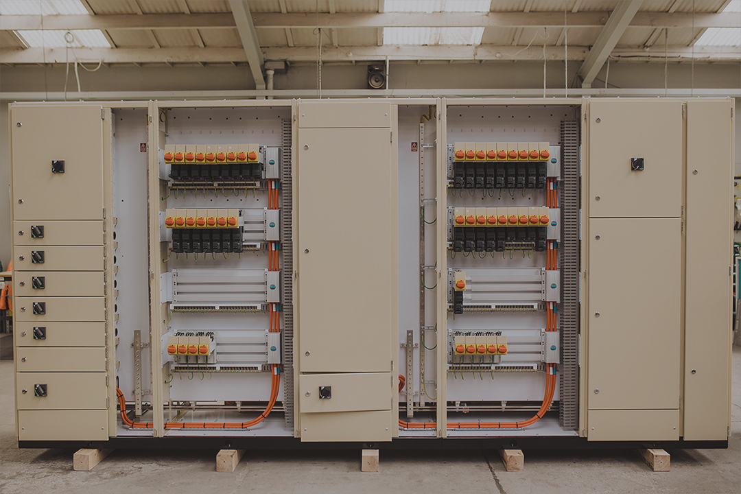
A drive can be integrated in a suitable assembly or housed separately. The decision should account for heat, EMC, harmonic effects, cable routes and maintenance. Avoid both blanket rules: “all drives go inside” and “drives can never go inside”.
3. Define how the process operates
- Local/off/remote operation and command priorities.
- Permissives, interlocks, trips and reset conditions.
- Loss-of-power and restoration behaviour.
- Emergency-stop and other safety functions, with the responsible safety designer identified.
- PLC I/O, network protocol, addresses and signal lists.
- Interfaces to vendor packages, field devices and SCADA.
A network protocol name is not a control philosophy. Agree who develops and validates the logic, who loads software, and who performs the site checks.
4. Specify the physical arrangement
Confirm the supply and fault requirements, form of separation, fixed or withdrawable arrangement, cable terminations, environment and access. The spare allowance must distinguish unpopulated space from equipped ways and usable electrical capacity.
5. Agree testing and handover
List the assembly verification records and functional tests. For a witnessed FAT, agree the test script, simulated signals, acceptance criteria and treatment of outstanding items. Confirm which external devices and software will actually be available for the test.
CWS supplies MCC manufacturing with project-specific documentation and interfaces. For a first introduction, read what an MCC does. For procurement, send this schedule with the single-line diagram and control philosophy so the proposal covers the same scope your installation team expects.
Sources checked for this update
Checked 30 September 2026. Apply the edition and instructions appropriate to the actual project and equipment.