
Extra backup equipment helps only if power can still reach the equipment that needs it. A good data centre switchboard brief explains what must stay running, how backup power reaches it, and how the system will be maintained and tested.
Start with what must stay running
List the IT equipment and supporting plant that must remain supplied during the agreed outages and maintenance work. Include cooling and controls where they are essential to keep the data centre operating.
Then describe what should happen when the normal supply is lost, a generator is used, or part of the system is taken out for maintenance. An uninterruptible power supply (UPS) can support its connected load during a supply interruption for its available backup time. The designer must confirm how the UPS, generators and switchboards work together.
CWS needs an approved power layout drawing, usually called a single-line diagram, and a clear explanation of these requirements before the board package can be finalised.
What N, N+1 and 2N mean
N means the capacity needed to supply the agreed load. With equal-sized units, it can also mean the number of units needed. “Redundancy” means adding spare equipment or another supply arrangement so an agreed problem can be handled without losing the load.
| Level | Simple meaning | Important limit |
|---|---|---|
| N | Enough capacity for the load, with no spare unit. | A required unit becoming unavailable leaves a capacity gap unless another approved supply can cover it. |
| N+1 | Enough capacity plus one extra unit. | It covers one unavailable unit only where the remaining equipment and connections can still supply the load. |
| N+2 | Enough capacity plus two extra units. | Extra capacity does not protect against every shared failure, such as a common output connection. |
| 2N | Two complete systems, each able to supply the full load. | Check whether a shared switchboard, control supply or other connection could affect both systems. |
| 2N+1 | Two full-capacity systems plus one extra unit. | The design must show where the extra unit sits and which system can use it. |
| 2(N+1) | Two full-capacity systems, each with its own extra unit. | The two systems still need their connections and shared dependencies checked. |
On a small screen, scroll sideways to read every column.
Always say what the label covers. A site might have N+1 generators and 2N UPS systems; that does not automatically make every part of the site equally redundant. The drawings and written scope are more useful than the label alone.
A simple example: three units are needed
In particular, 2N+1 should not be read as “a spare in each system”. Ask for the actual arrangement to be shown.
What Tier I to Tier IV mean
Uptime Institute’s Tiers describe how the complete data centre infrastructure performs. They cover more than the number of UPS units or switchboards.
| Tier | Main idea |
|---|---|
| Tier I | Basic infrastructure to support the IT equipment. Necessary maintenance can require an interruption. |
| Tier II | Extra critical power and cooling equipment provides spare capacity, but some maintenance can still require an interruption. |
| Tier III | Planned maintenance can be carried out on each required component or supply path without stopping IT operation. |
| Tier IV | Adds protection against an individual equipment failure or supply-path interruption, as well as planned maintenance. |
On a small screen, scroll sideways to read both columns.
Planned maintenance and an unexpected fault are different events. Tier III addresses the first; Tier IV also addresses the effects of the second. Risks can increase while backup equipment is already out for maintenance.
A 2N arrangement does not automatically establish Tier IV certification. The whole infrastructure, including power paths and cooling, needs assessment. Confirm any claimed certification and its scope separately.
Why two power feeds are not always independent
A and B are common names for two supply paths. For a 2N design, each must be able to carry the full agreed load when the other is unavailable.
Check what the two paths share. A common busbar, bypass, control supply, transfer device or cable route can create a point where one problem affects both. Two labelled incoming supplies alone do not prove independence.
Also confirm how the IT equipment connects. Equipment with two power connections may use both A and B. Equipment with one connection needs an agreed way to receive its backup supply; any transfer device also needs its own maintenance and failure assessment.
The useful question is: “If this part is unavailable, how does power still reach the equipment?”
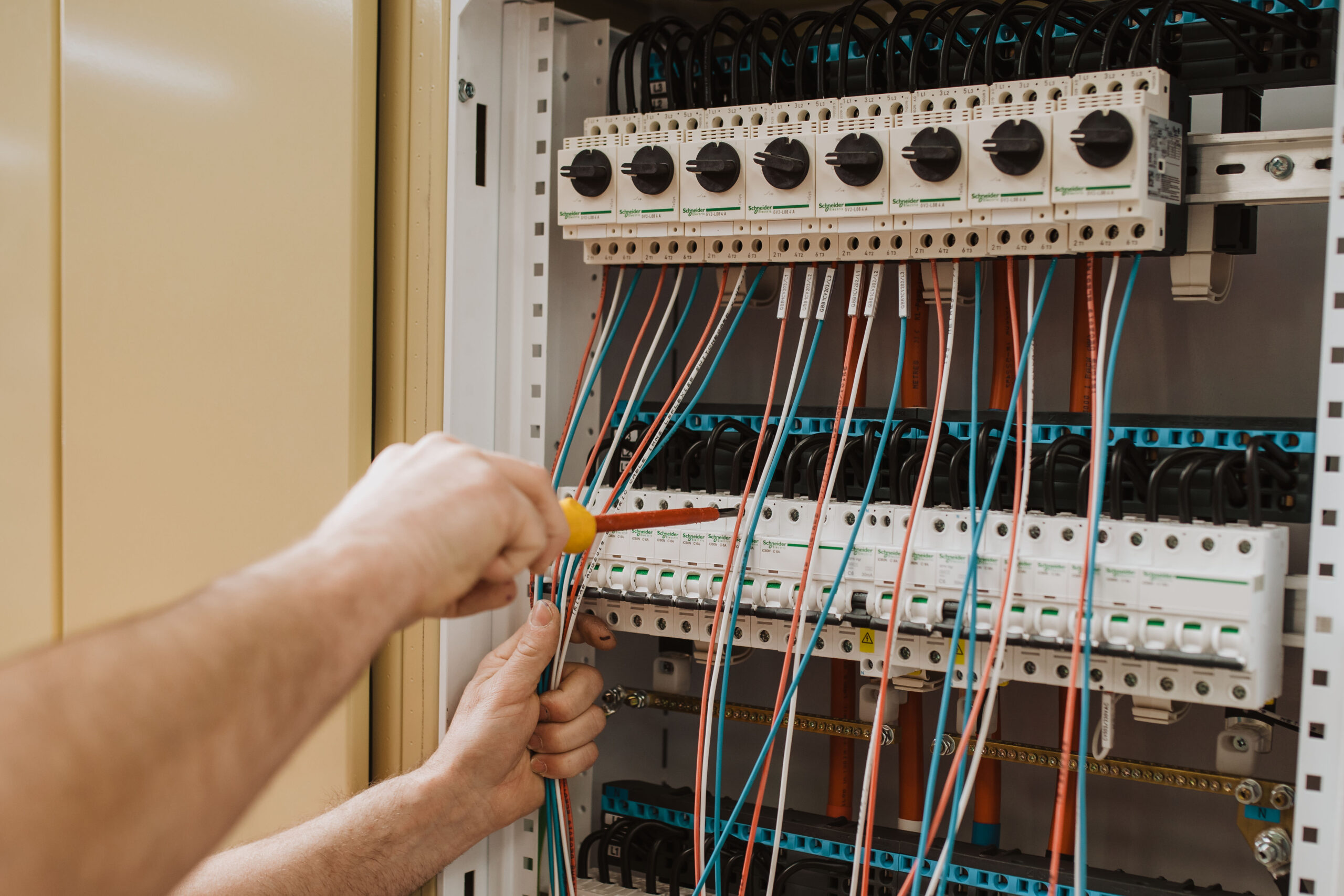
Plan maintenance without live work
The plan must account for every source, including UPS and auxiliary supplies. Internal separation such as Form 4 does not, by itself, make live work safe or prove protection against an arc fault.
The designer should identify the isolation boundaries and how equipment will be accessed, removed and replaced. This is part of the system design, not just a choice of enclosure or breaker.
Choose ratings for the real conditions
The board must suit the actual power sources, load and site conditions. This includes the current it must carry during normal operation and when another supply path is unavailable.
The electrical designer also checks fault current: the current that could flow during an electrical fault. A circuit breaker’s fault rating and the complete switchboard’s rating describe different things, so both need to suit the design.
Room temperature, cooling, load growth and the time spent in backup operation also matter. Give CWS these design inputs rather than relying on a generic “data centre” rating.
Agree what will be tested
Factory acceptance testing (FAT) checks the agreed switchboard functions before delivery. The plan should state what will be demonstrated, who will witness it and what counts as a satisfactory result.
- Check the agreed controls, alarms, indications and interlocks.
- Identify which external equipment is present and which conditions are simulated.
- Record findings and close out agreed remedial work.
- Supply the agreed drawings, settings and verification records.
Site testing then checks the installed cables, actual supplies and wider system interfaces. A factory test cannot prove the performance of equipment or connections that were not included in it.
Agree the FAT witness plan and the site tests together, including the specified outages and recovery conditions.
What to send CWS
- The approved power layout or single-line diagram.
- A list of loads, their required capacity and planned expansion.
- The backup arrangement and what each supply path must carry.
- The maintenance requirements and any Tier target or certification requirement.
- Site conditions, equipment layout and installation constraints.
- The required tests, documents and delivery programme.
Agree the scope for main switchboards, cooling and mechanical-plant MCCs and control interfaces against the same design.
The project designer defines how the complete power system must work. CWS uses those approved requirements to define the switchboard manufacturing scope and evidence to be supplied.
Sources checked for this update
Redundancy and Tier sources checked 1 October 2026; assembly source checked 30 September 2026. Apply the edition and instructions appropriate to the actual project and equipment.